
Silicone Compression Molding Design Guide
Design HCR/HTV silicone parts for compression molding. Review wall transitions, parting lines, flash, vents, undercuts, inserts, CTQs, tooling and first-article validation.
On this page
- First Confirm That Compression Molding Is the Right Process
- Wall Design: Avoid Unnecessary Stress and Filling Problems
- Parting Line and Flash Should Be Designed Around Critical Surfaces
- Venting and Filling: Give Trapped Air Somewhere to Go
- Undercuts: Flexible Parts Can Release, but There Is Still a Limit
- Inserts and Overmolding Need Location, Retention and Shutoff
Silicone remains flexible after molding, but the production tool is rigid.
That single fact explains many HCR/HTV compression-molding design decisions. A finished silicone part may stretch around an undercut, compress into a groove or flex during assembly, yet it still has to be formed, cured, separated from the tool and trimmed in a repeatable production process.
A good compression-molded design therefore balances two things:
- the flexibility needed in the final product
- the constraints of rigid tooling and repeat manufacturing.
This guide focuses on those DFM decisions. If you are evaluating WYD as a production supplier rather than looking for design guidance, use Silicone Compression Molding.
First Confirm That Compression Molding Is the Right Process
HCR/HTV compression molding is widely used for solid silicone parts, but it is not the default answer for every silicone geometry.
It can be a good fit for many:
- gaskets and seals
- covers and boots
- keypads
- grips
- mats and kitchen components
- bumpers
- molded trays
- other solid silicone parts.
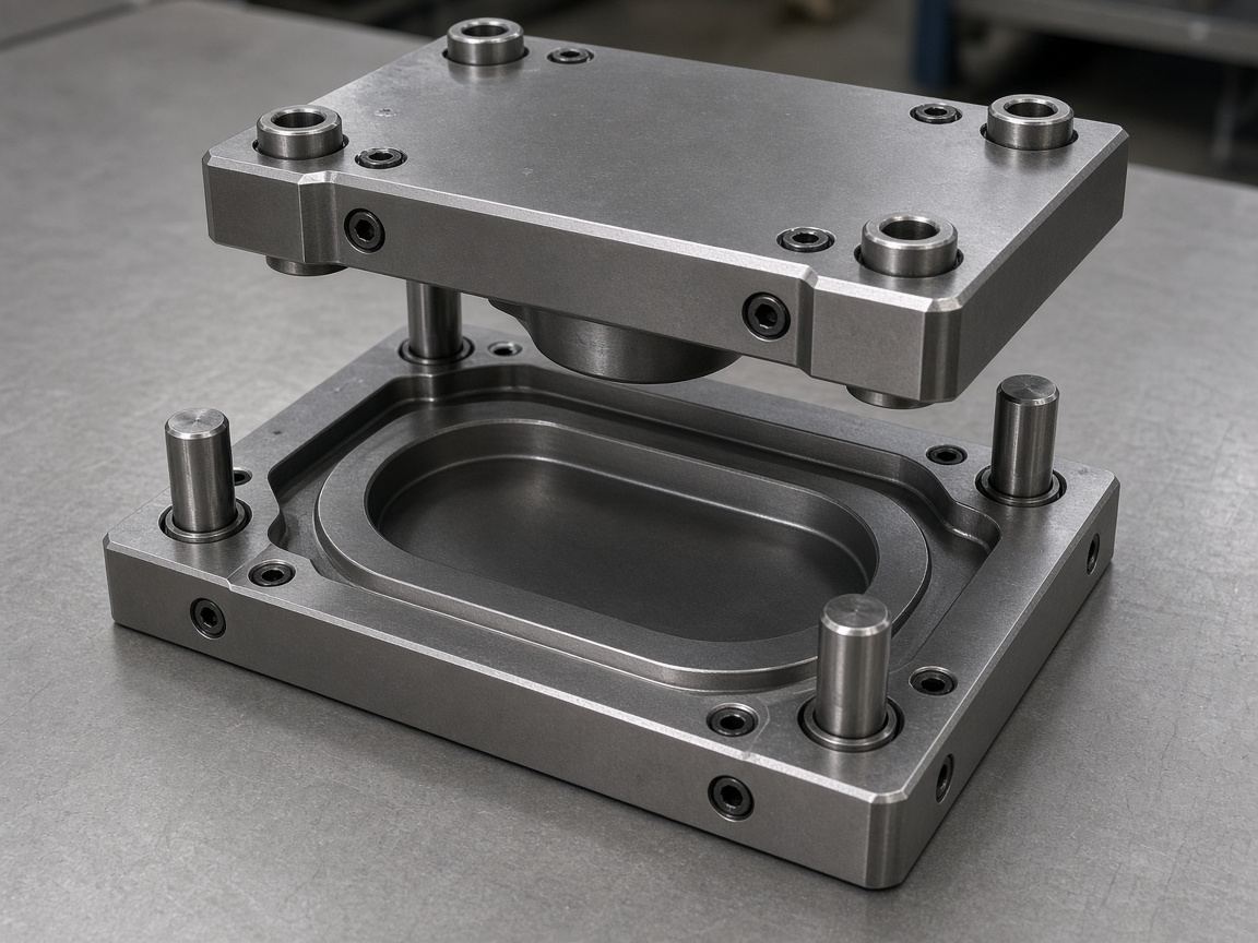
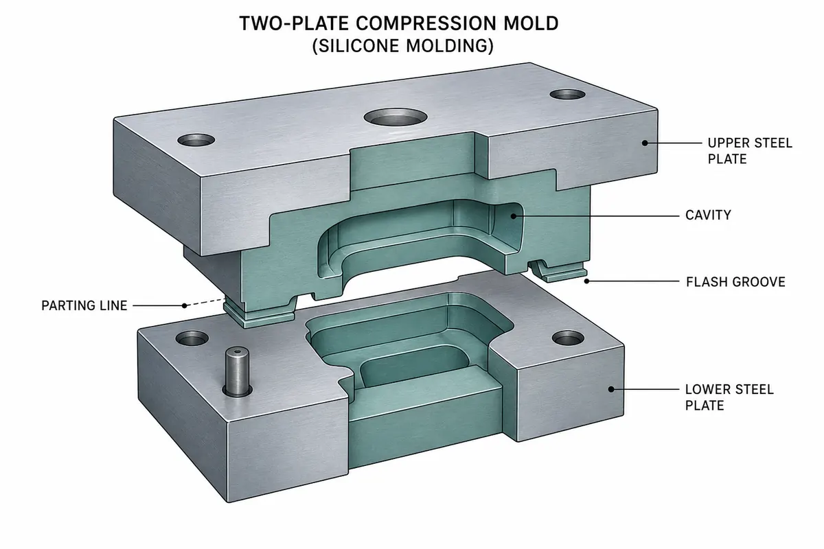
The process generally uses a prepared quantity of high-consistency silicone placed into heated production tooling. The tool closes, the material flows and cures, and the finished part is removed and trimmed as required.
Before designing specifically for compression molding, compare the alternatives.
Consider LSR when
- the required material system is LSR
- the geometry/process benefits from liquid injection
- thin or detailed sections, automation or production volume justify LSR tooling
- insert molding is better suited to an injection process.
Consider extrusion when
the product is a continuous tubing, cord or profile cross-section rather than a discrete molded part.
Consider RTV mold making when
the customer is buying a flexible casting mold made around a master pattern rather than a finished silicone component produced in metal tooling.
Process choice should be resolved before detailed tool DFM. Otherwise, the design may be optimized for the wrong manufacturing method.
Wall Design: Avoid Unnecessary Stress and Filling Problems
There is no single wall thickness that is correct for every compression-molded silicone part.
The useful question is how the section behaves during:
- material flow
- cure
- demolding
- use
- inspection.
Abrupt thick-to-thin transitions
Large section changes can complicate filling and cure behavior and may create local distortion or visible transitions.
Where the product allows it, use smoother changes rather than an abrupt step with a sharp internal corner.
Deep narrow pockets
A feature can look simple in CAD but create difficult flow or trapped-air conditions inside a rigid tool.
Ask whether:
- material can reach the end of the feature
- trapped air can escape
- the area can be demolded without tearing
- the tool can be machined and maintained.
Functional flexibility
Do not make the entire part thin just because one region needs to flex.
A product can use local geometry-webs, ribs, lips, bellows or reduced sections-to create motion while keeping other areas stable.
A silicone lid, for example, may need a flexible locating skirt but enough top structure to feel controlled during handling. A keypad needs compliant web geometry around each key while the surrounding base remains stable.
The correct wall strategy follows function.
Parting Line and Flash Should Be Designed Around Critical Surfaces
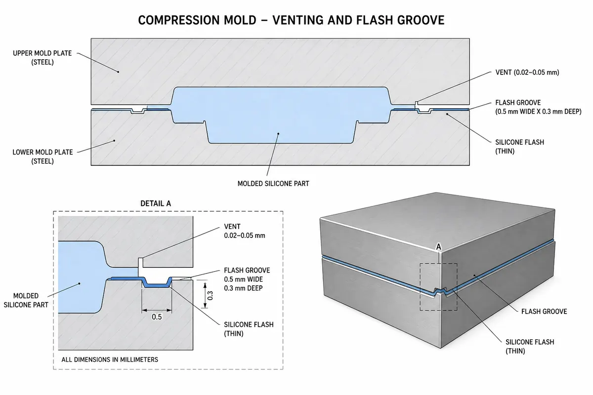
Compression tooling must open somewhere. That creates a parting line, and the process may produce flash that is later controlled or trimmed.
The parting-line decision is therefore not cosmetic only.
Avoid placing it without review across:
- sealing surfaces
- thin flexible lips
- electrical/contact interfaces
- highly visible cosmetic faces
- precise mating edges.
Gaskets and seals
A flash line across the sealing interface can affect performance more than flash on a non-functional outside edge.
Keypads
Flash near a web or conductive/contact feature can affect movement or assembly.
Covers and sleeves
Parting lines near ports, button openings or tight mating geometry can create fit problems.
Consumer products
The same line may be technically acceptable but visually undesirable on a grip or wearable surface.
DFM should define which surfaces are functionally flash-sensitive, which are cosmetic and which can accept normal trimming.
That is more useful than demanding "no flash" everywhere.
Venting and Filling: Give Trapped Air Somewhere to Go
As silicone fills the closed cavity, air must leave.
Risk areas can include:
- thin ribs
- long flow paths
- deep lettering
- blind pockets
- narrow end sections
- complex cavity transitions.
Poor venting can contribute to incomplete fill or local defects.
The correct vent strategy depends on the tool and geometry. It should be planned with:
- parting line
- overflow/flash control
- material flow
- trimming access.
Do not add cosmetic detail everywhere and assume production can fill it unchanged.
A deep logo at the end of a thin feature, for example, may need more review than the same logo on a broad flat surface.
For critical detail, first article should confirm that the production process reproduces it consistently-not only that the CNC tool contains the shape.
Undercuts: Flexible Parts Can Release, but There Is Still a Limit
Silicone flexibility can simplify features that would require slides or side actions in rigid plastic molding.
But "silicone stretches" is not a complete DFM rule.
When reviewing an undercut, consider:
- depth
- return angle
- local wall thickness
- radius
- distance the feature must stretch during release
- material tear behavior
- where the operator or automation applies force
- whether the same deformation repeats every production cycle.
A shallow retaining bead on a cover is a different problem from a deep closed undercut around a thin stem.
The correct question is not whether the part can be forced out once. It is whether the tool can release it repeatably without damaging the part, distorting critical geometry or creating excessive production handling.
If the undercut is too aggressive, options may include:
- changing the geometry
- changing the split
- using a removable/core feature
- selecting another tooling approach
- changing the manufacturing process.
Inserts and Overmolding Need Location, Retention and Shutoff
If a rigid plastic or metal component is molded with silicone, the insert becomes part of the tool design.
Review three separate issues.
1. Insert location
The insert must sit in the intended position while the mold closes and silicone flows.
Define:
- datums
- fixture features
- anti-rotation
- allowed movement.
2. Retention after molding
Depending on the product, retention can use:
- holes
- grooves
- undercuts
- wraparound features
- bonding/primer where validated.
Do not rely on vague "silicone adhesion" if the product will see peel, torque or pull.
3. Shutoff
Tool surfaces must control where silicone stops around the insert.
Poor shutoff can create flash on rigid cosmetic surfaces, fill unwanted holes or interfere with assembly.
For an overmolded grip, a torque test may be more meaningful than a simple pull test. For a protective edge, peel can reveal the weak termination.
Related service: Silicone Overmolding
Tolerances: Control the Dimensions That Control Function
Flexible silicone parts can be easy to over-tolerance.
A drawing with tight values on every dimension can create cost and inspection effort without improving the product.
Start with CTQs-critical-to-quality characteristics.
Examples:
- gasket sealing bead
- keypad contact location
- port opening in a protective cover
- insert position
- cavity pitch in a production tray
- critical bore or mating lip.
Then define how those CTQs will be measured.
Measurement method matters
A soft part can change shape depending on:
- how it is held
- measurement force
- fixture
- rest condition
- temperature/conditioning
- datum selection.
For critical flexible geometry, the measurement method should be agreed with the dimension.
A nominal tolerance without a repeatable method can create false rejection or mask a real fit problem.
Shrinkage belongs to the production system
Do not apply one universal silicone shrinkage allowance from a generic article.
Final dimensions can depend on the selected material, tool, process and geometry. Critical items should be validated on the production-intent sample and corrected through the controlled tooling process if required.
Cavity Count and Tool Layout Are Economic as Well as Technical Decisions
A multi-cavity tool can increase output, but more cavities are not automatically cheaper.
Tool layout affects:
- tool size
- press requirements
- preform/material loading
- venting
- cavity consistency
- trimming
- inspection
- handling
- tooling cost.
For a tray product, cavity count also changes the finished silicone part itself. A wider tray may need more support and can behave differently when loaded.
For small precision components, cavity-to-cavity variation may be part of the qualification plan.
The best cavity count balances:
- forecast volume
- tooling budget
- part size
- production capacity
- quality-control requirements.
If annual volume is uncertain, provide both the first order and realistic repeat forecast. Tooling can then be evaluated against the actual commercial program.
Surface Finish, Color and Cosmetic Requirements Need to Be Frozen Before Tool Completion
Silicone can reproduce tool texture and detail well, which means tooling finish is part of the product specification.
Before final tool finishing, define:
- matte/gloss target
- texture
- logo/deboss/emboss
- visible parting line
- acceptable trim witness
- color reference
- critical cosmetic surfaces.
A rendering cannot fully show how texture, color and parting-line placement will look on a flexible molded part.
Use first article or approved physical sample to establish the final cosmetic reference where appropriate.
Color should also be reviewed under a defined lighting/reference method rather than described only as "match the picture."
First Article: Validate the Product and the Production Process
A first article from production-intent tooling should verify more than overall appearance.
Depending on the part, approval may include:
- CTQ dimensions
- fit to mating hardware
- Shore hardness using an agreed method
- parting-line/flash condition
- surface finish
- color
- insert location
- pull/peel/torque function
- sealing
- keypad movement
- demolding
- packaging/deformation risk.
Some tests belong to the customer because they depend on the final device or use condition.
For example, a silicone gasket can be dimensionally correct and still require leak validation in the customer's full enclosure. A cover can match its drawing but still need assembly validation on the real housing.
The approved part, drawing and inspection plan should together form the production reference for repeat orders.
Related page: Silicone Quality Control
What to Send for Compression-Molding DFM
A useful engineering review should include:
- 3D model
- 2D drawing if available
- part function
- material or Shore requirement if already specified
- mating components
- critical dimensions
- sealing/cosmetic surfaces
- inserts
- operating environment
- first production quantity
- annual/repeat forecast
- required functional tests
- target market/documentation.
If the design is early, identify which dimensions are fixed and which can still change.
Need a Manufacturing Review?
For process sourcing and quotation, use Silicone Compression Molding or send the model through Contact WYD.
For a broader finished-product program, see Custom Silicone Products Manufacturer.
Ready to order custom silicone molds?
Send your drawing, sample or project requirements for DFM and quotation.