
A 3D file can be dimensionally correct and still be a poor tooling release.
DFM asks whether the geometry can be manufactured, demolded, measured and repeated using the intended process. CAD work is different: CAD creates or changes the geometry itself.
That distinction matters when a buyer is comparing quotations. A supplier may identify a risky undercut during DFM without including the modeling work needed to redesign it.
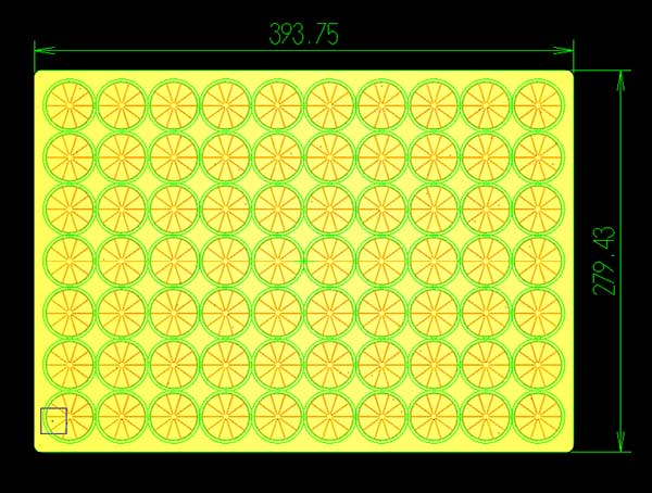
DFM Review and CAD Work Are Different Deliverables
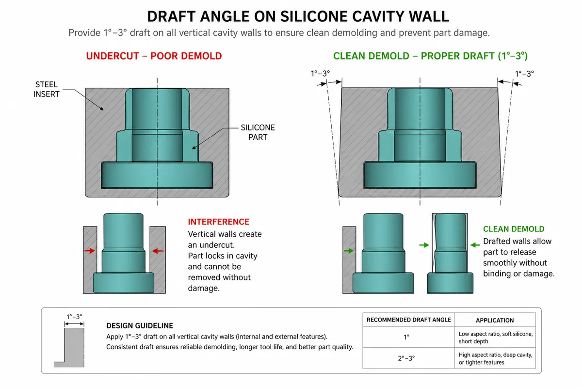
A useful DFM review should identify decisions, not quietly redraw the product.
The review can classify findings as:
- must change — likely to block tooling, demolding or function
- recommended — improves production consistency or inspection
- optional — cosmetic or preference-driven
- open question — needs buyer input or prototype evidence.
CAD modification starts after those decisions are understood.
Minor CAD work may adjust a wall, radius, logo depth, slot, lip or locating feature.
Full modeling is a different scope when the buyer only has artwork, reference images, a sketch or an incomplete model.
If the physical object is the primary source, the task moves into reverse engineering, not ordinary CAD correction.
A Mold-Ready File Must Define More Than Shape
Before tooling, review the features that can create failure during manufacturing or use.
Depending on the product, this can include:
- parting-line location
- undercuts
- thin-to-thick transitions
- flash-sensitive surfaces
- local tear-risk geometry
- inserts or shutoffs
- logo and small detail
- cavity layout
- demolding direction
- mating interfaces.
The correct list depends on the intended process.
A flexible casting mold, a compression-molded part and an injection-molded part do not create the same tooling risks. Process-specific detail belongs in the relevant process page; this page should explain the decision boundary rather than repeat every manufacturing process.
Review the Product Where Failure Would Matter Most
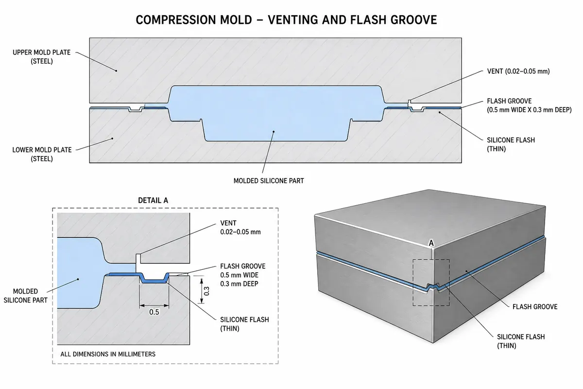
DFM should begin with the critical function.
If a surface seals, do not place a seam there without understanding the consequence.
If a cavity must align with filling equipment, pitch and datum matter more than a non-critical outside dimension.
If a flexible lip controls fit, define how that lip is measured and installed.
If a logo is a selling feature, confirm whether its depth and line width are compatible with filling and release.
This is where CTQs become useful: they tell the tooling team which dimensions and surfaces must not be treated as ordinary geometry.
Flexible Silicone Needs a Measurement Condition
A tolerance without a measurement method can create false precision.
Flexible parts can move under:
- caliper pressure
- unsupported weight
- stretching
- fixture pressure
- installation on the mating component.
For critical dimensions, define:
- the datum
- relaxed or installed state
- support or fixture
- measurement tool
- location
- functional test where dimensions alone are not enough.
This is also why a prototype should be approved against actual use when fit, loaded behavior or demolding is the real requirement.
For sample planning, use Silicone Prototyping.
DFM Should End With Clear Decisions
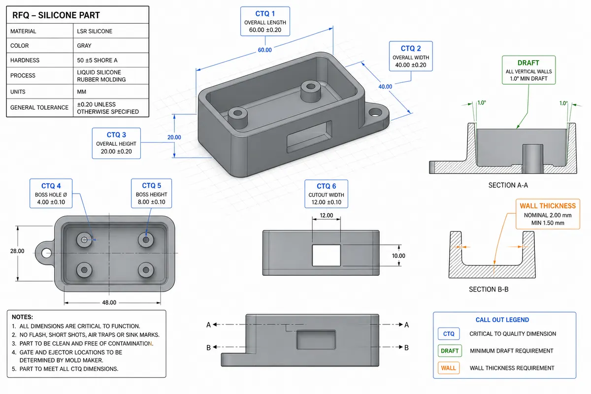
Before tooling release, the buyer should be able to see:
- what changed
- what stayed unchanged
- which risks remain open
- what the prototype must prove
- which revision is approved
- which CTQs require controlled inspection.
A long checklist is not the objective.
The objective is a design that engineering, tooling, quality and purchasing interpret the same way.
What to Send for a DFM Review
Send:
- current STEP/STP or best available model
- 2D drawing if available
- what the part or mold must do
- mating components or interface data
- critical dimensions
- expected quantity
- intended manufacturing route if already selected
- known failure or concern.
If the design is still too incomplete for DFM, the correct next step may be product development rather than tooling review.
CAD / 3D Modeling Fee
CAD / 3D modeling fee: USD 50.
DFM review and CAD/modeling work should still be treated as separate scope items so the buyer knows what is being reviewed and what geometry is being changed.
Send a project for review
Send the file or sample, the function, and the quantity.